
Top seller

Riggatec M8 Flange Clamp
€7.90
*
incl. tax,
plus shipping costs
 Express delivery possible
Availability:
Delivery time: 1-3 days
Delivery time: 1-3 days

Riggatec Beam Clamp Black 1t - 75 - 230 mm
€59.00
*
incl. tax,
plus shipping costs
Availability:
Delivery time: 1-3 days
Delivery time: 1-3 days

Riggatec M10 Flange Clamp
€7.90
*
incl. tax,
plus shipping costs
Availability:
Delivery time: 1-3 days
Delivery time: 1-3 days

Riggatec Beam Clamp Black 3t - 80 - 322 mm
€99.00
*
Availability:
Delivery time: 1-3 days
Delivery time: 1-3 days

Doughty T29700 Flange Clamp
€7.98
*
incl. tax,
plus shipping costs
Availability:
Delivery time: 1-3 days
Delivery time: 1-3 days

Riggatec M12 Flange Clamp
€8.90
*
incl. tax,
plus shipping costs
Availability:
Delivery time: 1-3 days
Delivery time: 1-3 days

Riggatec Beam Clamp Black 2t - 75 - 230 mm
€64.90
*
incl. tax,
plus shipping costs
Availability:
Delivery time: 1-3 days
Delivery time: 1-3 days

Riggatec Beam Clamp Black 5t - 90 - 320 mm
€129.00
*
Availability:
Delivery time: 1-3 days
Delivery time: 1-3 days
12
Articles
No results were found for the filter!
Riggatec M12 Flange Clamp
Riggatec M12 Flange Clamp
The Riggatec flange clamp with threaded socket is ideal for easy attachment by clamping to steel girders. For VdS-Systems securing tags are required from DN 65. The hollow ground of the...
€8.90
*
incl. tax,
plus shipping costs
Availability:
Delivery time: 1-3 days
Delivery time: 1-3 days
Riggatec M10 Flange Clamp
Riggatec M10 Flange Clamp
The Riggatec flange clamp with threaded socket is ideal for easy attachment by clamping to steel girders. For VdS-Systems securing tags are required from DN 65. The hollow ground of the...
€7.90
*
incl. tax,
plus shipping costs
Availability:
Delivery time: 1-3 days
Delivery time: 1-3 days
Riggatec Beam Clamp Black 1t - 75 - 230 mm
Riggatec Beam Clamp Black 1t - 75 - 230 mm
Riggatec beam clamp The Riggatec beam clamp is used for the safe, quick and easy creation of an anchor point for holding loads and lifting gear. Ideal as a quick solution for urgent work and...
€59.00
*
incl. tax,
plus shipping costs
Availability:
Delivery time: 1-3 days
Delivery time: 1-3 days
Riggatec Beam Clamp Black 2t - 75 - 230 mm
Riggatec Beam Clamp Black 2t - 75 - 230 mm
Riggatec beam clamp The Riggatec beam clamp is used for the safe, quick and easy creation of an anchor point for holding loads and lifting gear. Ideal as a quick solution for urgent work and...
€64.90
*
incl. tax,
plus shipping costs
Availability:
Delivery time: 1-3 days
Delivery time: 1-3 days
Riggatec Beam Clamp Black 3t - 80 - 322 mm
Riggatec Beam Clamp Black 3t - 80 - 322 mm
Riggatec beam clamp The Riggatec beam clamp is used for the safe, quick and easy creation of an anchor point for holding loads and lifting gear. Ideal as a quick solution for urgent work and...
€99.00
*
Availability:
Delivery time: 1-3 days
Delivery time: 1-3 days
Riggatec Beam Clamp Black 5t - 90 - 320 mm
Riggatec Beam Clamp Black 5t - 90 - 320 mm
Riggatec beam clamp The Riggatec beam clamp is used for the safe, quick and easy creation of an anchor point for holding loads and lifting gear. Ideal as a quick solution for urgent work and...
€129.00
*
Availability:
Delivery time: 1-3 days
Delivery time: 1-3 days
Doughty T29700 Flange Clamp
Doughty T29700 Flange Clamp
A flange clamp suitable for use with parallel or tapered flange beams. This Lindaptor uses a hexagon head, high tensile cup point screw for secure grip.
€7.98
*
incl. tax,
plus shipping costs
Availability:
Delivery time: 1-3 days
Delivery time: 1-3 days

ELLER Beam Clamp 1 Ton - 75 - 230 mm
ELLER Beam Clamp 1 Ton - 75 - 230 mm
: WLL (kg): 1000 kg • WLL (t): 1 t • Material: Steel • Finish: Powder Coating • Colour: Black • Maximum Width (mm): 75 mm • Minimum Width (mm): 230 mm • Weight:...
€86.50
*
Availability:
Delivery time: 3-5 days
Delivery time: 3-5 days

ELLER Beam Clamp 2 Ton - 75 - 230 mm
ELLER Beam Clamp 2 Ton - 75 - 230 mm
: WLL (kg): 2000 kg • WLL (t): 2 t • Material: Steel • Finish: Powder Coating • Colour: Black • Maximum Width (mm): 75 mm • Minimum Width (mm): 230 mm • Weight:...
€62.90
*
incl. tax,
plus shipping costs
Availability:
Delivery time: 3-5 days
Delivery time: 3-5 days

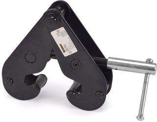
EUROLITE Girder Clamp 3000 kg black
EUROLITE Girder Clamp 3000 kg black
Beam clamp for steel beams, maximum load WLL 3000 kg Suitable as temporary installation point for steel beams (L-beams, I-beams) • Quick and tool free installation of rigging points for spots,...
€139.00
*
Availability:
Delivery time: 3-5 days
Delivery time: 3-5 days

EUROLITE Girder Clamp 1000 kg black
EUROLITE Girder Clamp 1000 kg black
Beam clamp for steel beams, maximum load WLL 1000 kg Suitable as temporary installation point for steel beams (L-beams, I-beams) • Quick and tool free installation of rigging points for spots,...
€79.90
*
Availability:
Delivery time: 1-3 days
Delivery time: 1-3 days
Riggatec M8 Flange Clamp
Riggatec M8 Flange Clamp
The Riggatec flange clamp with threaded socket is ideal for easy attachment by clamping to steel girders. For VdS-Systems securing tags are required from DN 65. The hollow ground of the...
€7.90
*
incl. tax,
plus shipping costs
Availability:
Delivery time: 1-3 days
Delivery time: 1-3 days